We entered the 3-week period with an alpha prototype and a material list for our build idea for the next prototyping session.
The first two days of the sprint we mainly focused on getting an overview of the project and set strategies for prototyping as well as goal setting.
First sprint goals:
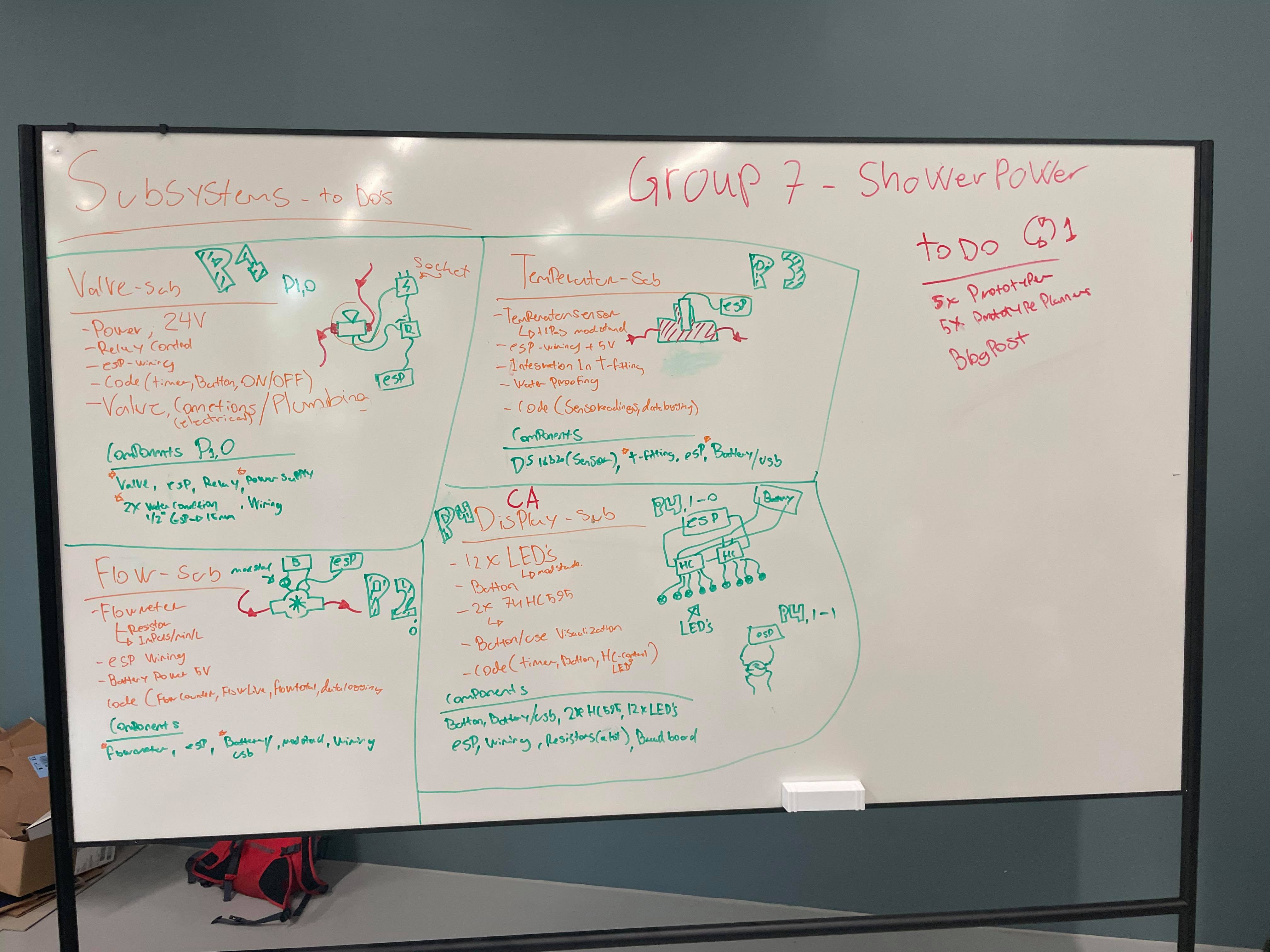
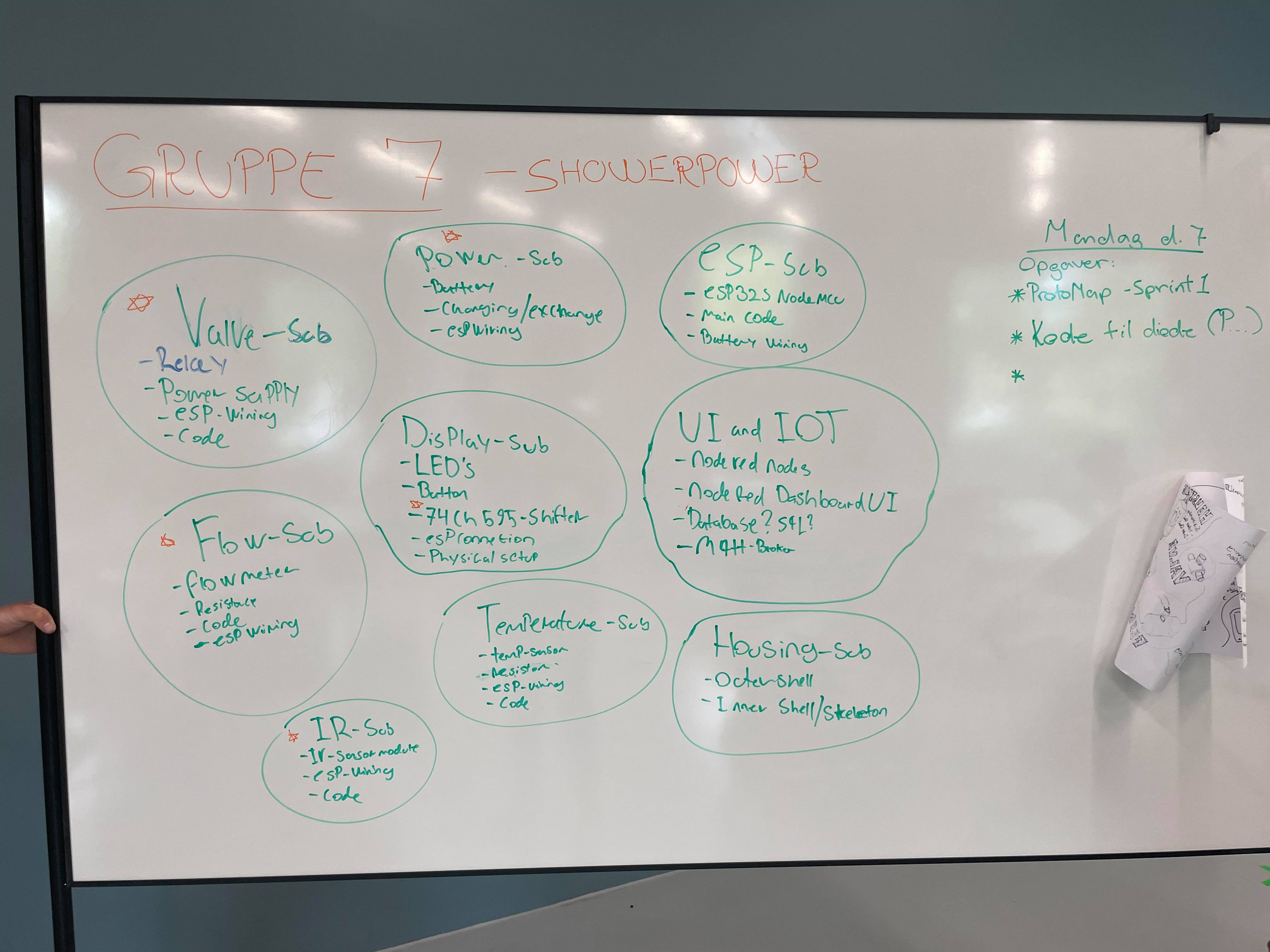
- Get a clear refined list of subsystems (by a F/M tree)
- Assemble the new iterations of all the subsystems and get them to work jointly
- Come up with the first draft of the design of the integrated system
- Mainly focus on low fidelity prototyping of the housing
We came up with the following strategies to prototype the different subsytems:
- For the fist sprint we would focus mainly on isolated subsystems while focusing on the integrated system on the second sprint.
- For the first sprint we will do low fidelity physical prototypes and hand sketched ideas for concepts while on the second sprint we will focus on higher fidelity prototypes as well as virtual prototyping via 3D-CAD models of the housing
Next step was to define the different prototype sessions.
We started by dividing each subsystem into four different prototypes while planning each session with components and connections between.
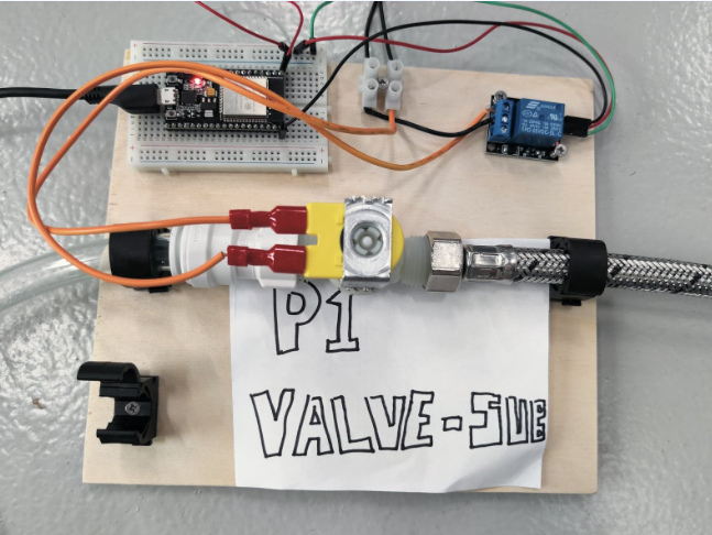
- P1 being the valve subsystem
- P2 being the flow subsystem
- P3 being the temperature subsystem
- P4 being the display subsystem
- (We would also consider P5 as the button in connection to the display subsystem)
We divided each of these prototype between the group members.
The day started on a low note as the first package delivered only contained some buttons. That means we still need almost everything to start moving the process along. We needed a plan for the rest of the day:
The group split up into subgoups.
One group worked on the motion sensor.
One group worked on the integrated code.
One group worked digital prototyping via CAD.
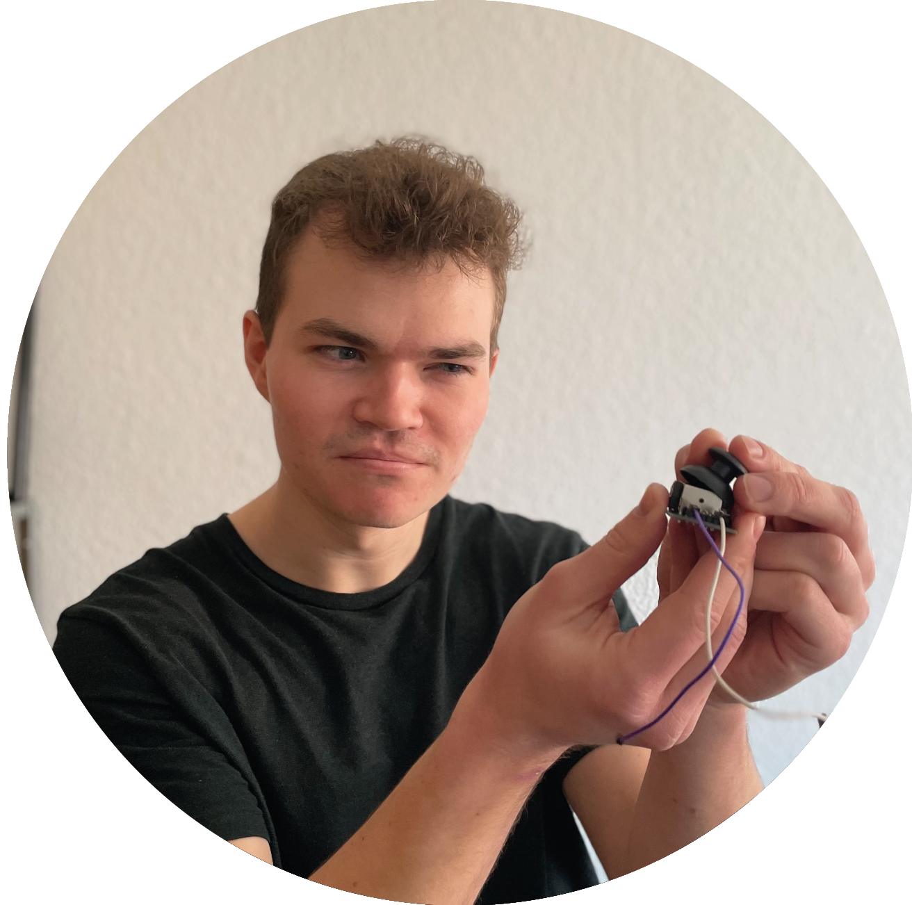
One group worked on waterproofing the button.
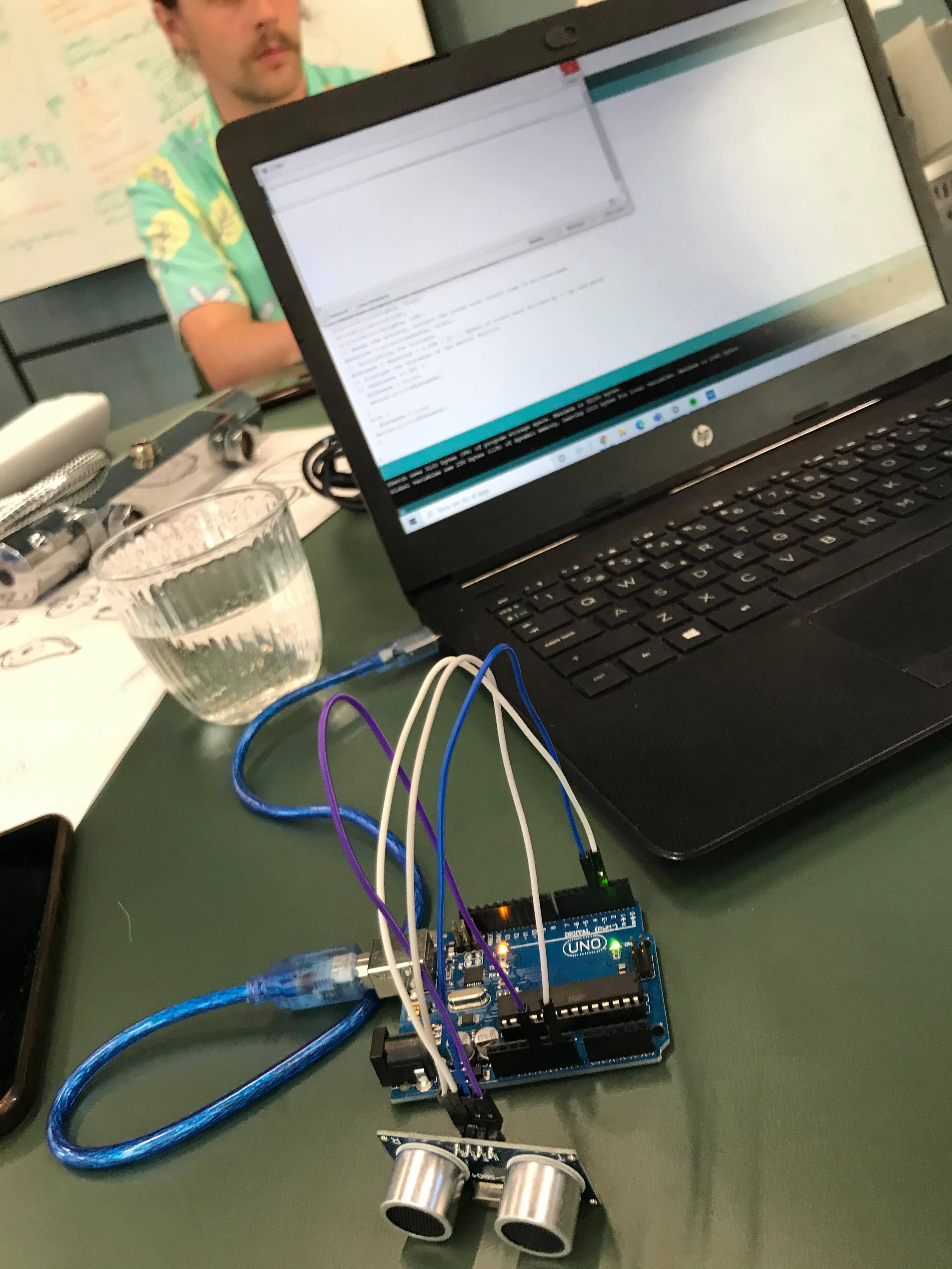
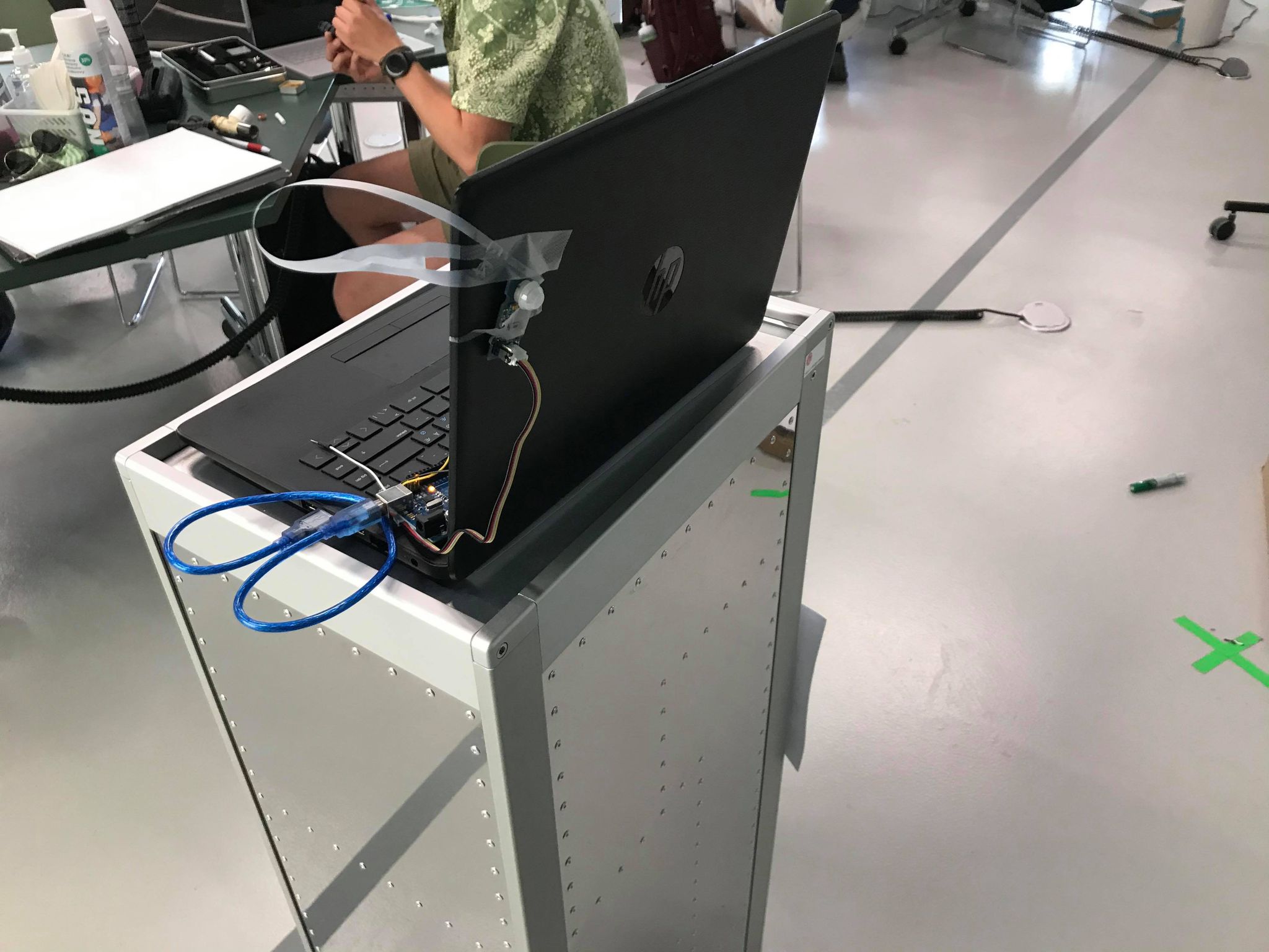
Since the group ran into problems because of the delayed components we needed to jump a bit ahead in the prototyping phase. The sensor was not supposed to be a core component in our system but was one of the thing we could test at the moment.
Firstly we needed to know if the system would get interferences from the movement of the water in front of it.
We simply tested this with a simple code (output 0 if there is something in front of the sensor and 1 if there weren't).
As expected we found that there were some sporadic outputs when we ran the test in front of the water, luckily the results were indeed sporadic which meant that we could code our way out of the problem.
We solved the issue by creating a value called "i". When the sensor did not pick up anything it would add to "i" (i = i+1). The loop would then repeat with the new value of "i". If the sensor would sense something i n front of it, it would be reset (i=0). If "i" would be allowed to add up to 10, we could then be reasonably sure that there is nothing in front of the sensor, as there had not been registered anything in 10 consecutive loops, and the valve would be engaged (water turned off).
An issue we found were that the current ultrasonic sensor is not waterproof while also requiring a clear sight of the scanning area (could not be put in a clear shell).
We did though find that a waterproof ultrasonic sensors does exist, which led us to conclude that the current setup would be sufficient in proving that our concept would work in praxis.
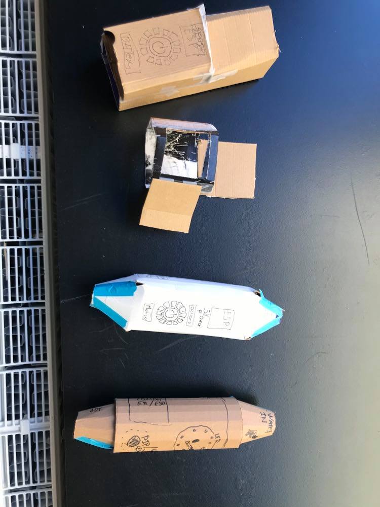
We were curious on how we would setup all of the subsystems into the shell. We therefore began a low fidelity prototyping session where we made a series of differently shaped housings. Not only to do some form-design but also to get an idea of how we would arrange the said subsystems.
We speculated on a couple of things during this process.
We were curious on how waterproof we could expect the inside of the shell to be and furthermore how close we could safely place these subsystems to the waterflow. This would be a speculation we could only validify at later stages of the project when we are to create the integrated system.
Secondly we played with the idea of making the house round or giving it a square surface. These different solutions would of course also rely on the shape of the entrails as well as the button.
The system would need a visual timer so that the user would be able to get an idea of how much time is left when in the shower.
We did a couple of animations to try to visualize a design. Some of the designs were inspired by the FN world goal.

.gif)
This morning we finally got the rest of our components. We started the day by getting an overview of all the components. After we set a built plan for the integrated system (just to make sure we had all the components we needed) we started prototyping on the subsystems. The team split up once again:
- One group worked on testing the temperature subsystem
- One group worked on testing the display subsystem
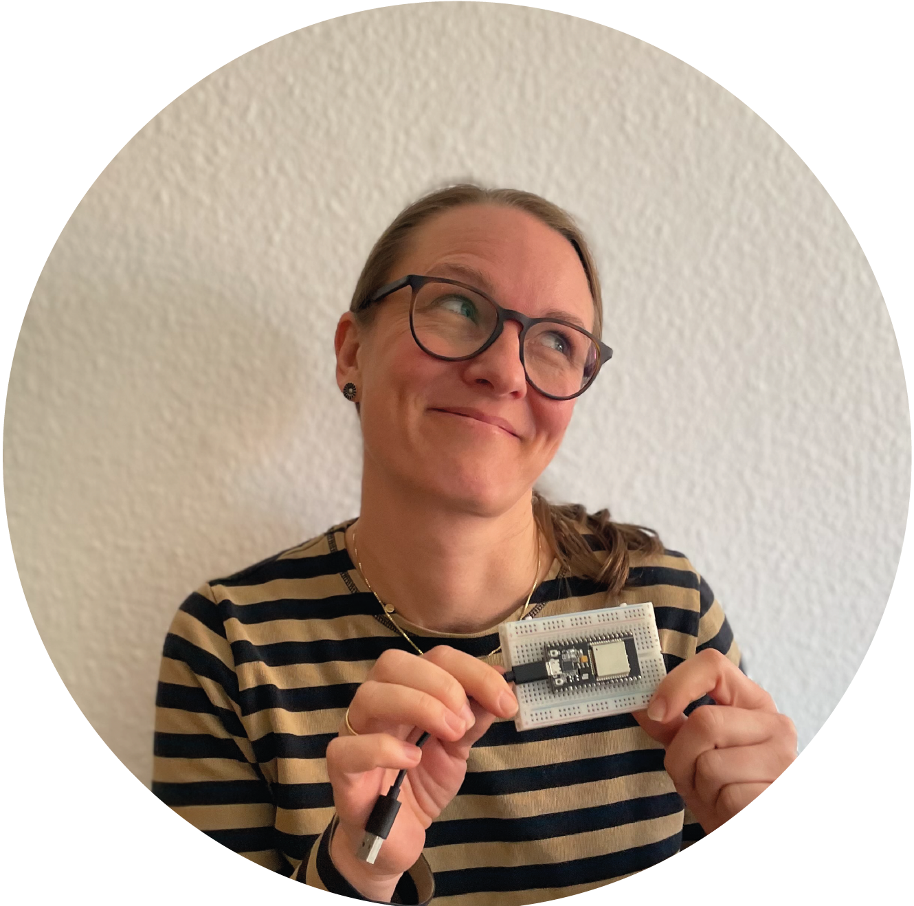
- One group continued on the sensor subsystem - now with the IR sensor
- One group worked on the UI of the app
When we received our package with all the materials in it we quickly realized that the size of the integrated build would be a lot bigger than we imagined. Therefore we needed to rethink some of the subsystems to cut down on the amount of space they would take up.
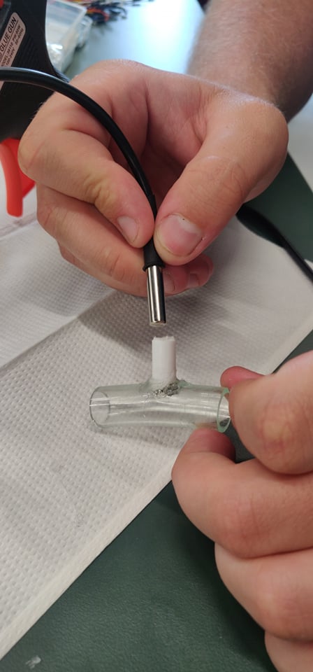
The most ideal system to rework would be the temperature subsystem. Our first idea of the build would have included a T-fitting pipe piece. We then came up with the idea of trying to get the probe directly fitted into the pipe without the need of a fitting piece.
The P3 test included testing if the probe-directly-into-pipe build would be waterproof. We would also build the subsystem with the aforementioned T-fitting pipe just to test how effectively it would proof the water.
From the test we could conclude that it would be possible to fit the sensor into the pipe. We did though only test the pipe section as an isolated part of the system so it is yet to be seen whether it would still prove waterproof at when fully integrated into the system.
Since we now had the IR sensor we could redo the test from yesterday with the IR sensor to see which sensor would be the best fit for our prototype. We already knew that the pros of using an ultrasonic sensor would be that it gave a relatively clear indication of whether or not a person was in front of the sensor and it could distinguish between the motion of the running water and a person.
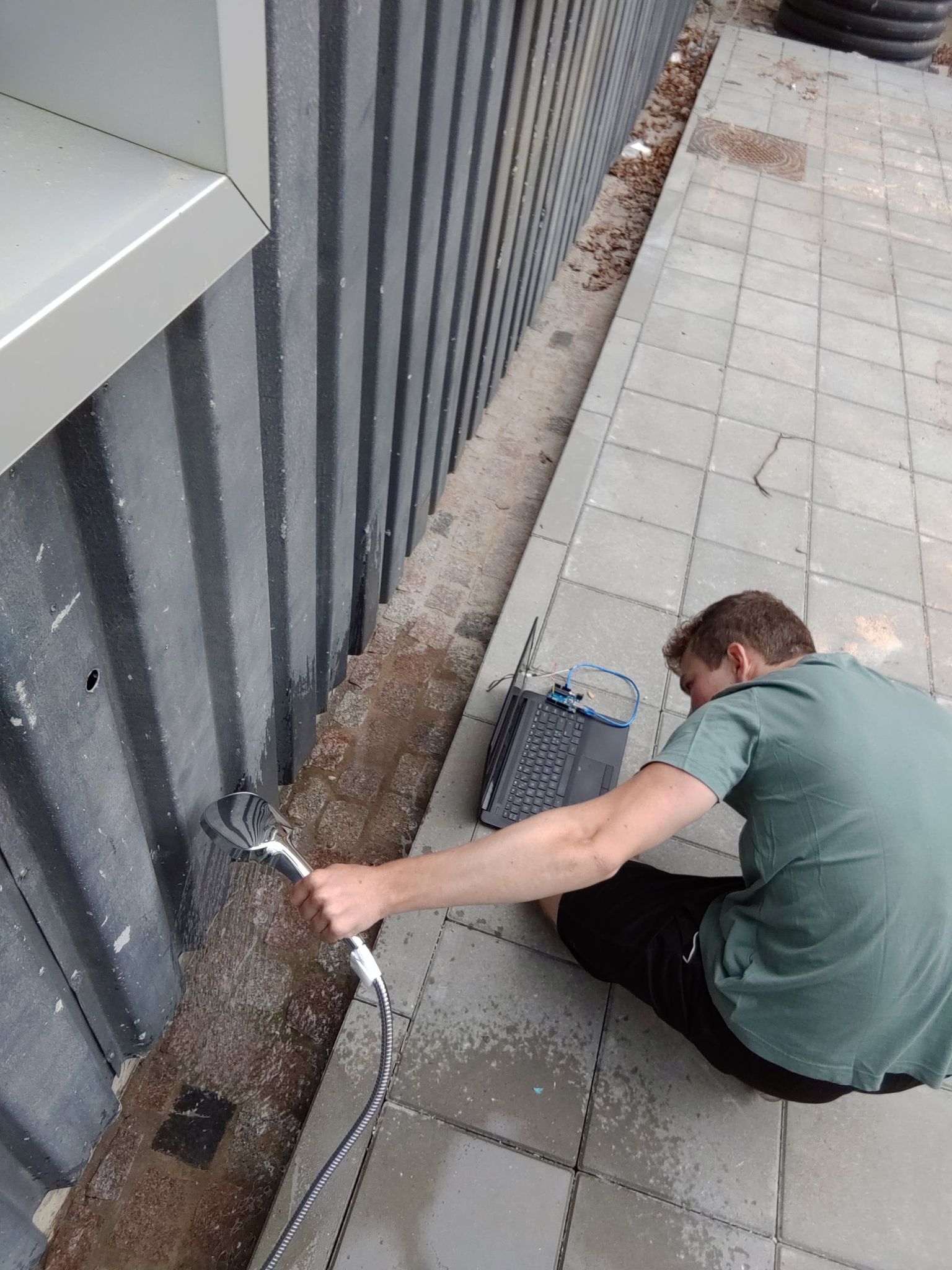
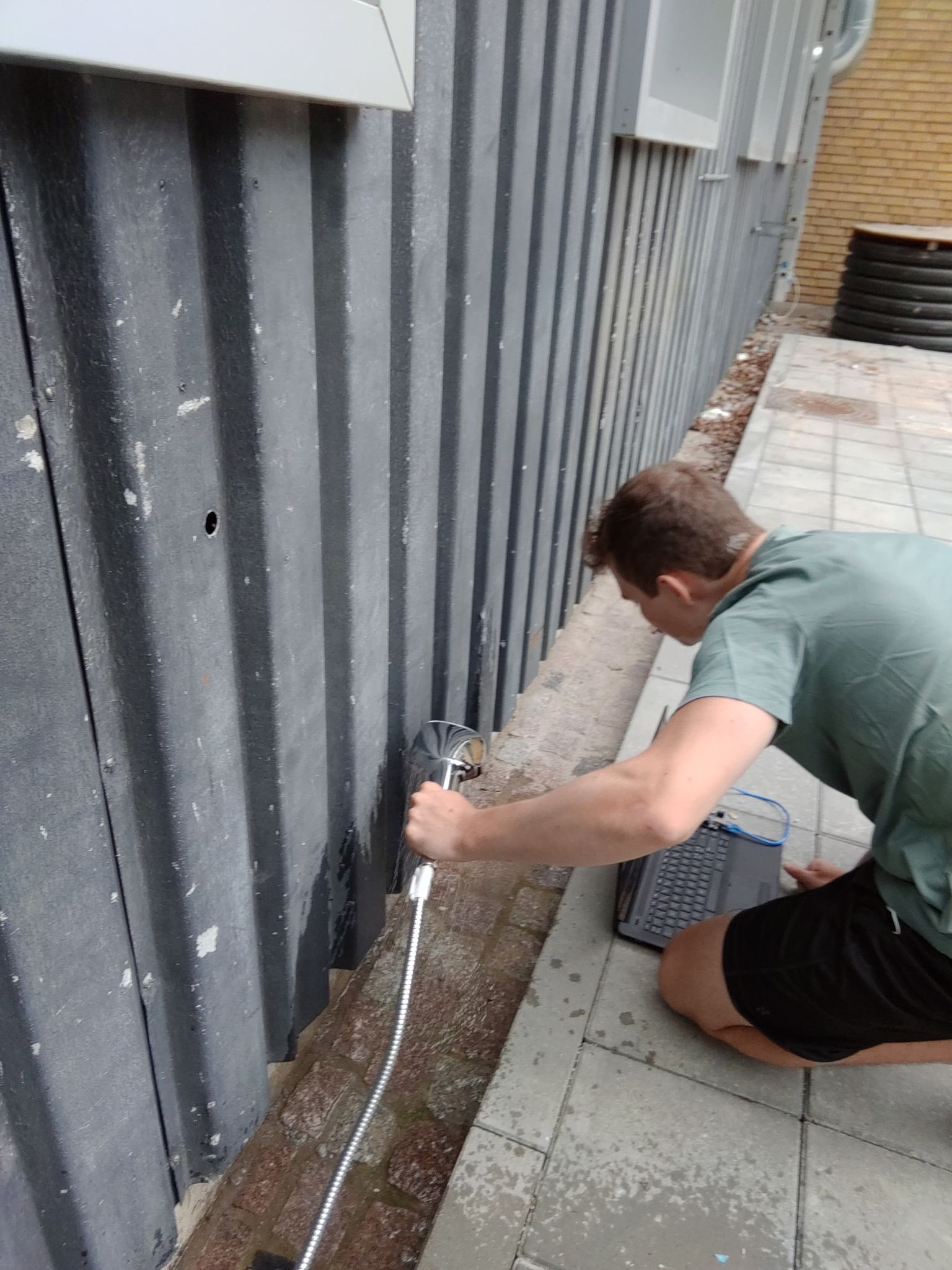
We redid the tests with the IR sensor and quickly realized that this sensor was a lot more sensitive than the ultrasonic. We ran into a couple of problems with the IR sensor from the very beginning. Firstly the sensor that we got could only be adjusted to a radius of 6 meters. This would mean that the sensor would not turn off when the user would leave the shower as the person would still be in view of the sensor. Secondly the sensor would not pick up the person if they stood still in front of the sensor. This would of course mean that the user would need to be in constant motion in front of the sensor to keep the water turned on.
We also did the test with running water in front of the sensor. In this case it picked up movement and would output that someone was in front of the sensor. The readings of the IR sensor were not nearly as sporadic as the ultrasonic sensor which would make it a lot more difficult to sort out the inputs.
It is also worth remembering that the PIR sensor needs to be perfectly still, which is why the computer with the attached sensor is placed on the ground/table on the pictures below.
Because of all these factor we chose to include the ultrasonic sensor in the integrated system instead of the IR sensor.
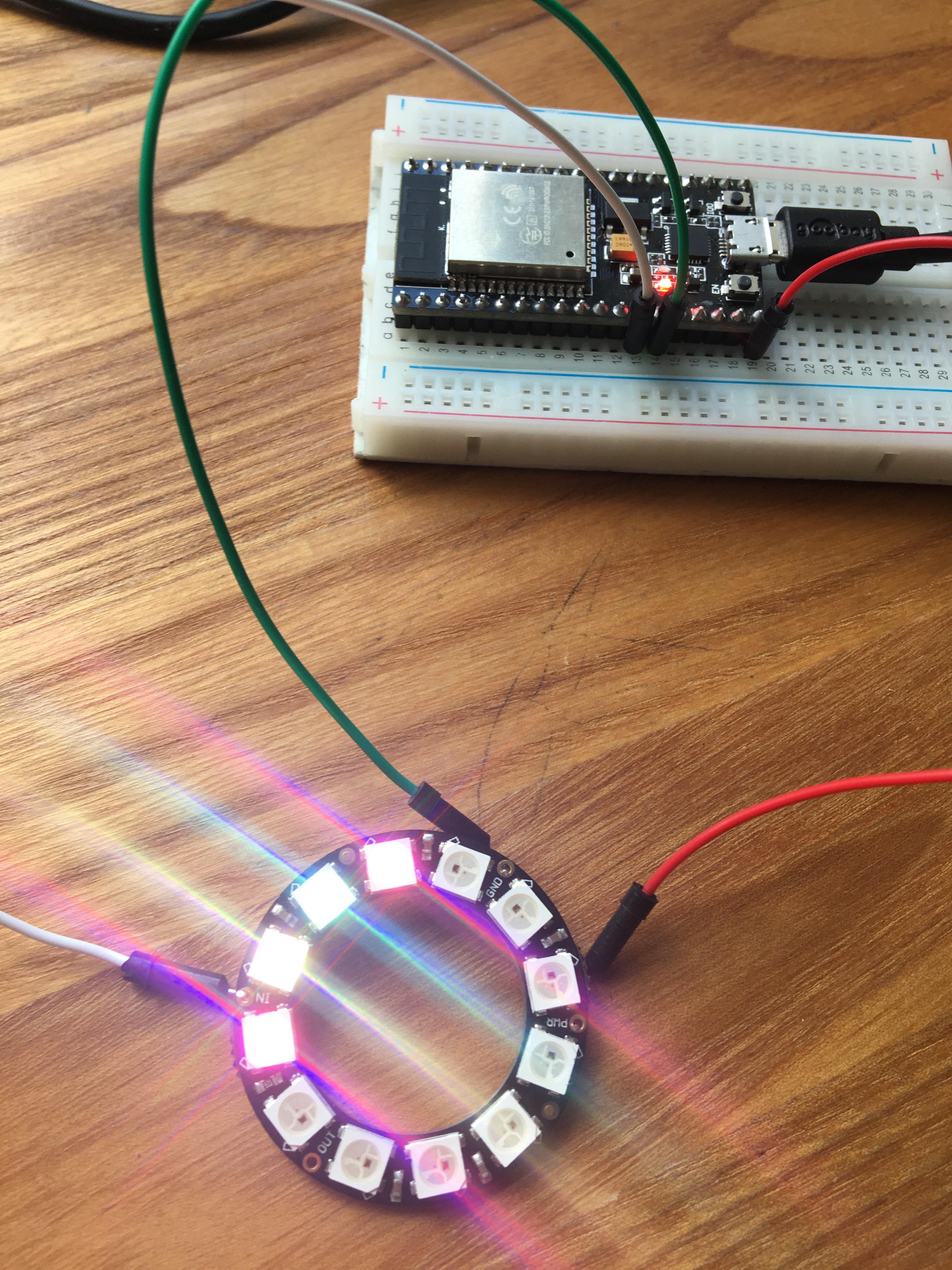
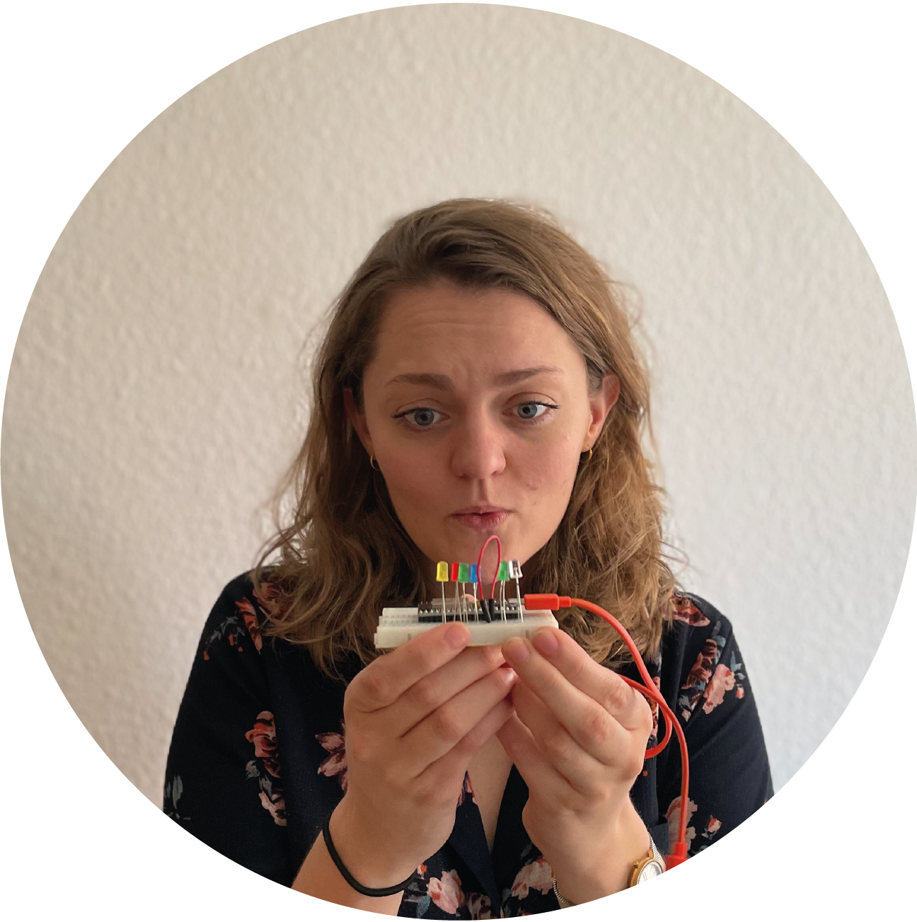
The first ideation of this prototype was formed by 12 LED lights to indicate how much time would be left until the valve would shut off.
We quickly found that having 12 LED's running on the same ESP would require a lot of wiring.
Our ESP would not be able to support this amount of wires.
We solved this problem by implementing a 74hc595 chip into the system.
This chip would be able to reduce the amount of wires needed to be connected directly to the ESP.
We proved that the concept works with a setup of 8 LED's. We found that the breadboard in general would be pretty cluttered with wiring when using large quantities of LED's.
This was not necessarily a deal breaker for the subsystem but we did feel like we would be able to improve the system by lowering the complexity of especially the wiring.
Therefore we decided to replace the line of LED's with a Neopixel ring instead.
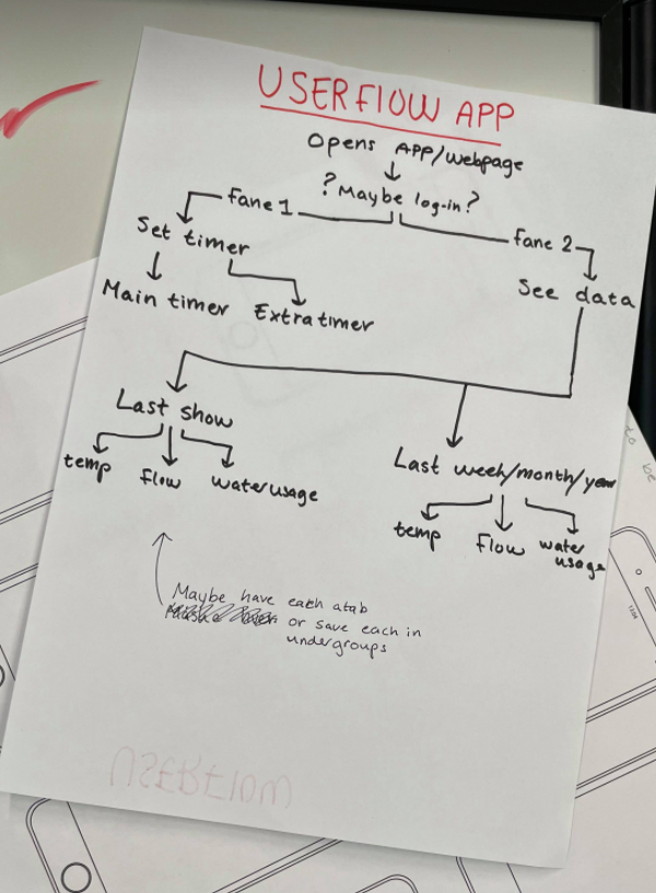
We knew that the UI would need a couple of feature for certain but was still unsure what the setup would look like.
By using a simple diagram we could map out how we would want the interface. Our design goals required us to include the controls of the shower in the interface as well as having a data log. We decided to divide these two interfaces into two tabs. The data log would have further menus where the user would be able to choose between seeing the data from the last shower session or a general statistic of the week/month/year.
We started the day out by getting a full view of what tasks needed to be finished today to finish off the first sprint. It was our goal for the first sprint to make sure that the subsystems were tested and ready to be integrated into the full system.
We had previously in the alpha prototype gotten a smaller valve to work with the ESP setup.
With the new prototype we simply changed the smaller valve for a larger one.
The valve worked as it should without the need of any tweaks in the code or in the wiring.
For further testing we would need to connect the valve to the button. When creating the integrated system we will also need to adjust the sensor data to control the valve.
Because of our upsizing of the prototype we needed to get a new flow measurer. The measurer we ordered worked by having an infrared LED and an infrared sensor. With each turn of the propeller a barrier would block the connection between the LED and the sensor.
The hardware of the flow measurer created some challenges for us when trying to get it to work. Firstly we wouldn't get a reading when trying to test the flow. When dissecting the the measurer as we were not sure how it worked. On first intuition we thought that the LED was broken and since it was an infrared and we couldn't get visual confirmation on whether or not it was on. After some testing with electrical flow we concluded that nothing was wrong with the LED as it did carry current through it. Another problem we ran into was an uncertainty of what amount of resistance was needed. When using the recommended resistance we would not get any output. When lowering the resistance we finally got a clear reading. This meant that the flow measurer could now be integrated into the full system.
A general problem we ran into during this test was that the measurer used infrared light to signal an output. This made it quite difficult for us to troubleshoot the measurer.
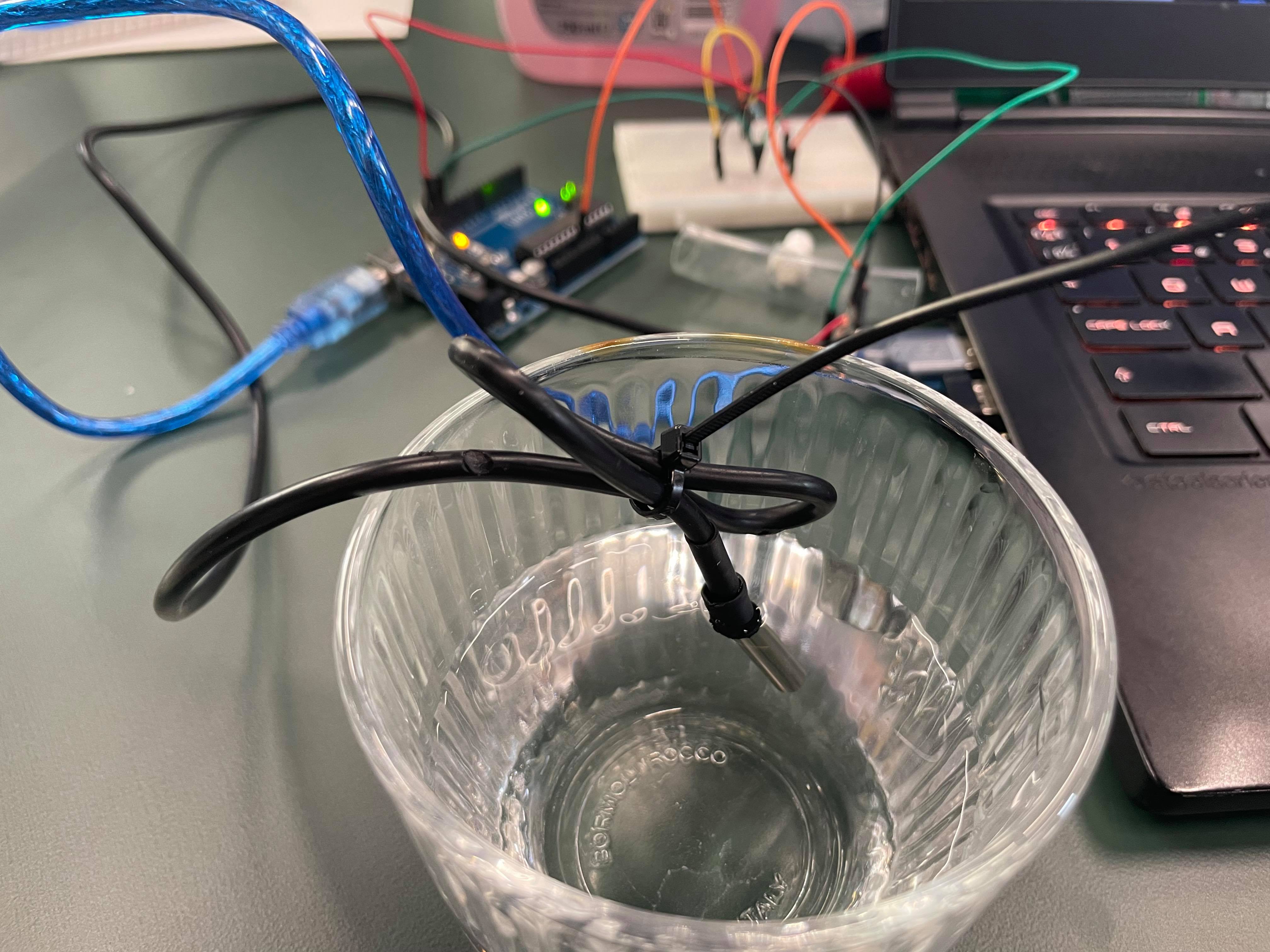
We had tested the temperature probe could be fitted directly into the piping while still keeping waterproof. We still needed to make sure that the probe would pick up the correct temperature reading when installed this way. Therefore we set up a simple test to compare temperature readings when the probe was installed into the pipe and without.
We would use a glass of water as the control temperature. We needed to make sure that the temperature reading of the water would be the same when the probe did reading from inside the piping as it would from reading directly in the water.
Luckily the reading were indeed identical which meant we could safely green light the temperature subsystem for the integrated system.
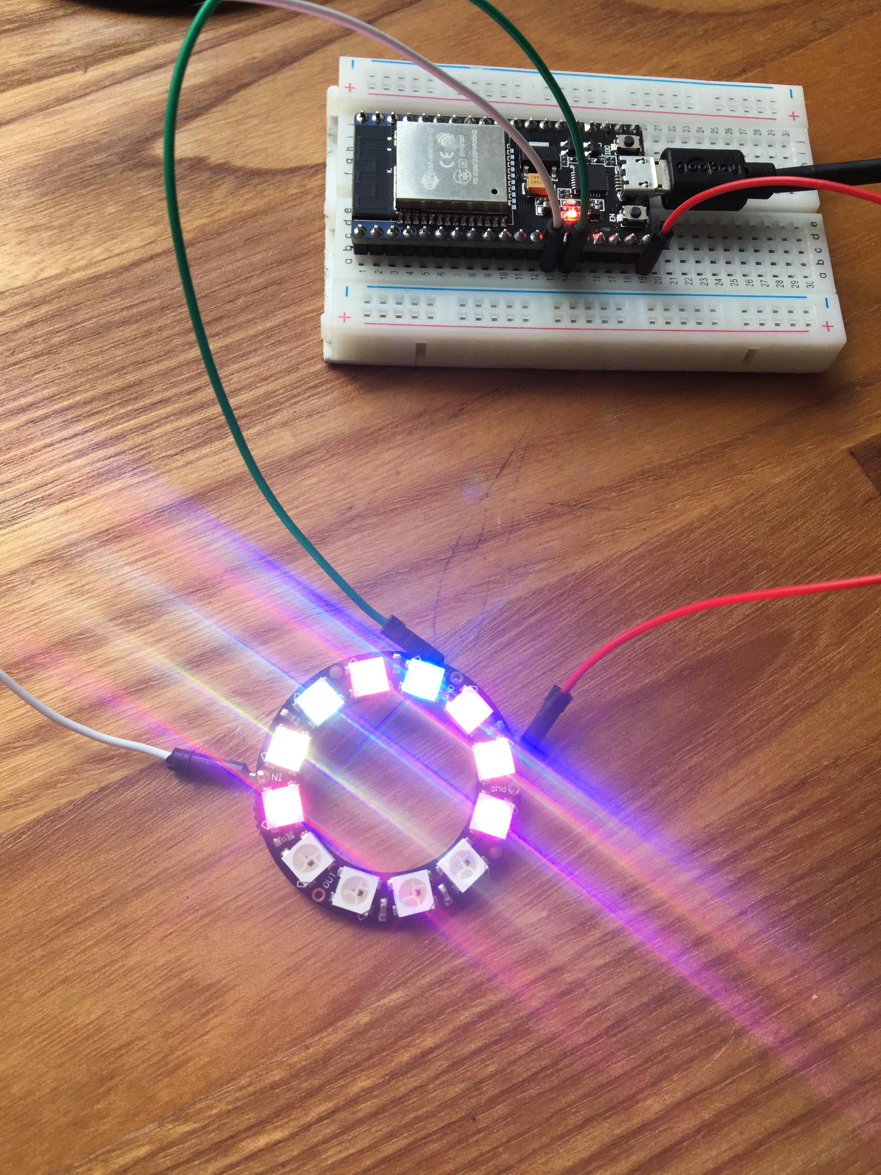
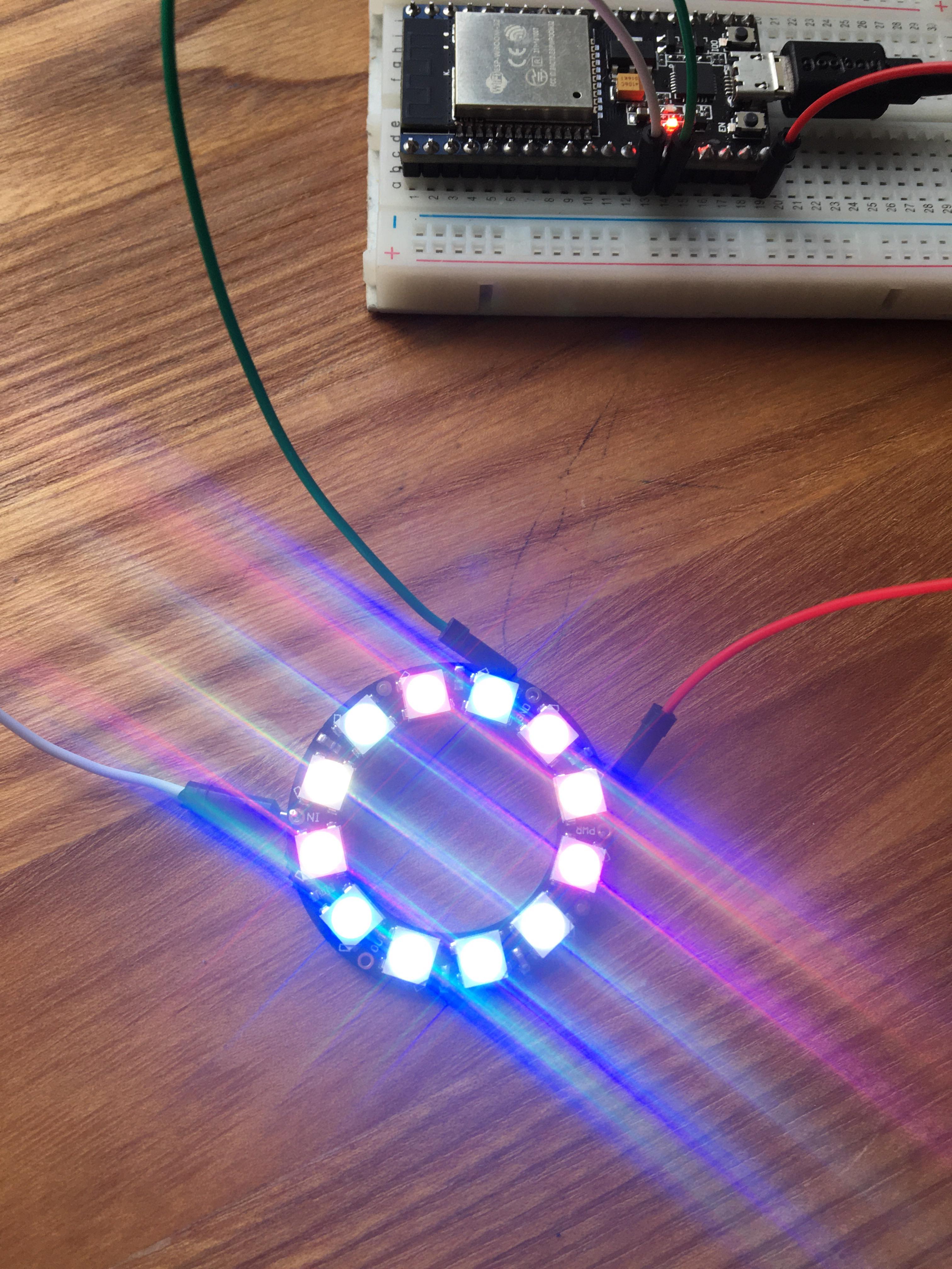
We needed to write a new code for the new neopixel LED ring.
We also needed to figure out what esthetic we would want for the display. Would we want the LED's to shine with white light and then integrate colored foil into the housing in front of the lights? Would we want the LED's to shine colored light? And we also needed to figure out which colors would be best. We were previously inspired by the UN world goals wheel in the design of the wheel and would also test if replicating those colors would give the esthetic we wanted.
We tried different permutations but decided that we would make our choice when we could see the full integrated system as well as how the product would look in its use space.
We started the day by evaluating the goal we had set for sprint two at the start of the 3-week period. We ended up adding a couple more goals that we needed to reach at the end of the sprint.
The day was afterwards used to try to assemble the piping of the integrated system.
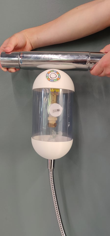
This time around, time was spend fitting our first outer shell around the plumbing components which are very crucial for the dimensions of the product as a whole. This prototype consist of two almost identical bowls which makes up the top and bottom of the shell. Bridging the gap between the two cups are plastic sheets, which are fitted snugly into grooves. These sheets did however not stay on very well and would curl of, making this particular moment of the process very time consuming.
What we did learn was how big the product could become which provokes some considerations regarding the setup and shape of the outer shell.
Yesterday we mainly focused on assembling the piping components. Today we would be focusing on integrating the electrical components and the code.
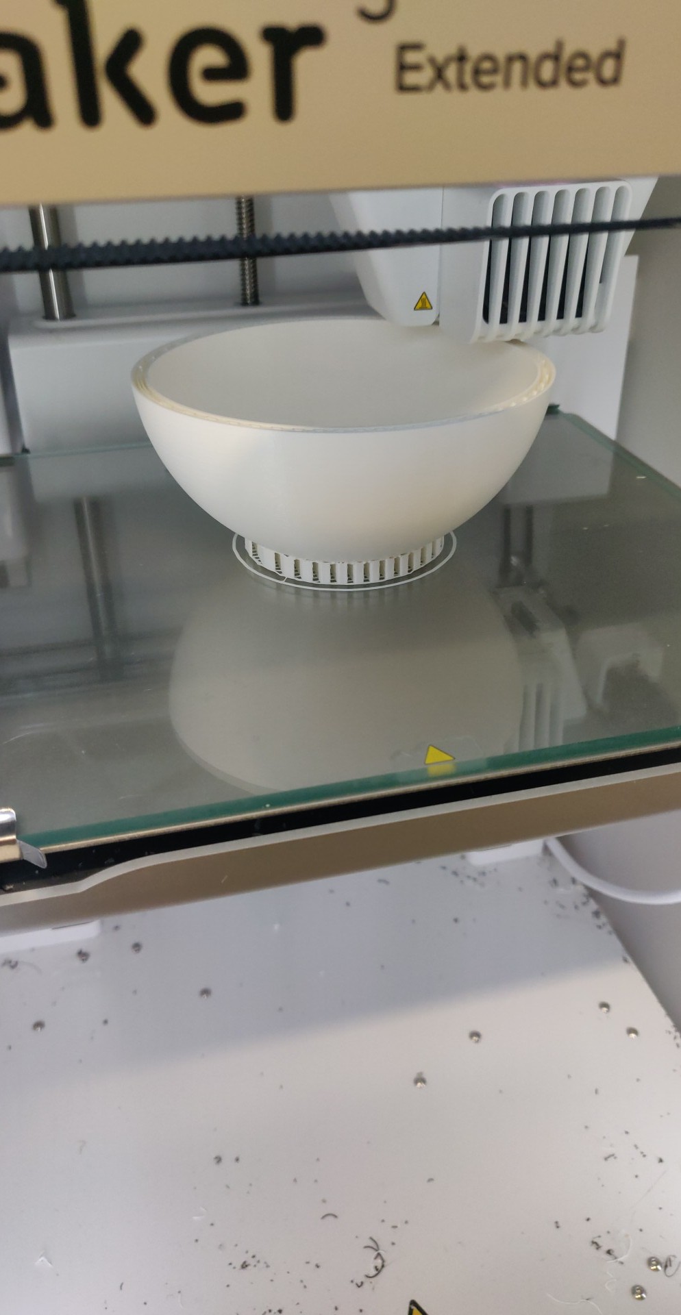
Yesterdays build gave us a clear view of the size our prototype would have, but it still needed a few details. We needed to design a hole in the shell for the button/LED setup as well as the motion sensor. Secondly we would need an inner "skeleton" where the electrical components would be fastened. We designed This new housing design and began 3D printing.
Simultaneously another part of our group would work on assembling all the code in one single integrated code. We wanted the valve to open from one push of the button, and close again from a double tap of the button. We ran into a couple problems as it wouldn't be as easy as we thought to code the button behavior we wanted. We got some very peculiar bugs when testing the setup. One time the setup would work on the laptop, but if the laptop got its charger plugged in it would crash.
Today we ran into trouble. Two of our subsystems began acting out when we tried to integrate them.
Firstly the flow sensor. Last sprint we got the flow sensor to work after many rigorous attempts. When we today tried to hook it up with the same test today and we could not gen an output. We tried troubleshooting on all parameters but in the end the worst case scenario happened; one of the components broke. We had an idea that we might have ruined the sensor during an earlier test and that the results we got from last sprint was inaccurate data anyways. We ordered a new sensor right away and will expect it to arrive at the first day of the last sprint. This incident will mess up our schedule a bit.
The second troubling subsystem was the ultrasonic sensor. We found out that the sensor only works with a 5V input. This means that it did work perfectly when hooked up to the UNO (which outputs 5V), but when hooked up to the ESP (that only outputs 3.3V) the sensor would not work. The integrated systems battery was running on 6V and we would not dare try to use too many volts. We could also not use a voltage regulator as it required the difference in voltage changed to be larger than 2V. 6V to 5V would not exceed this.
Our solution was to incorporate a MKR-WIFI-1010 (an arduino with a build in ESP32).
Today we also made progress with the database.
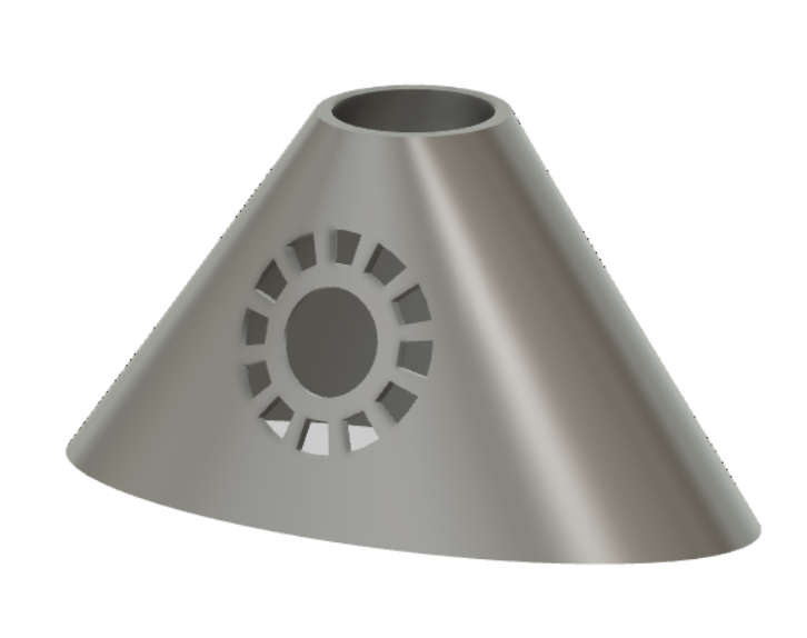
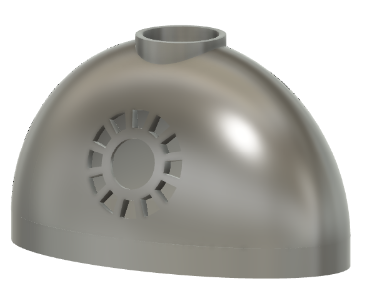
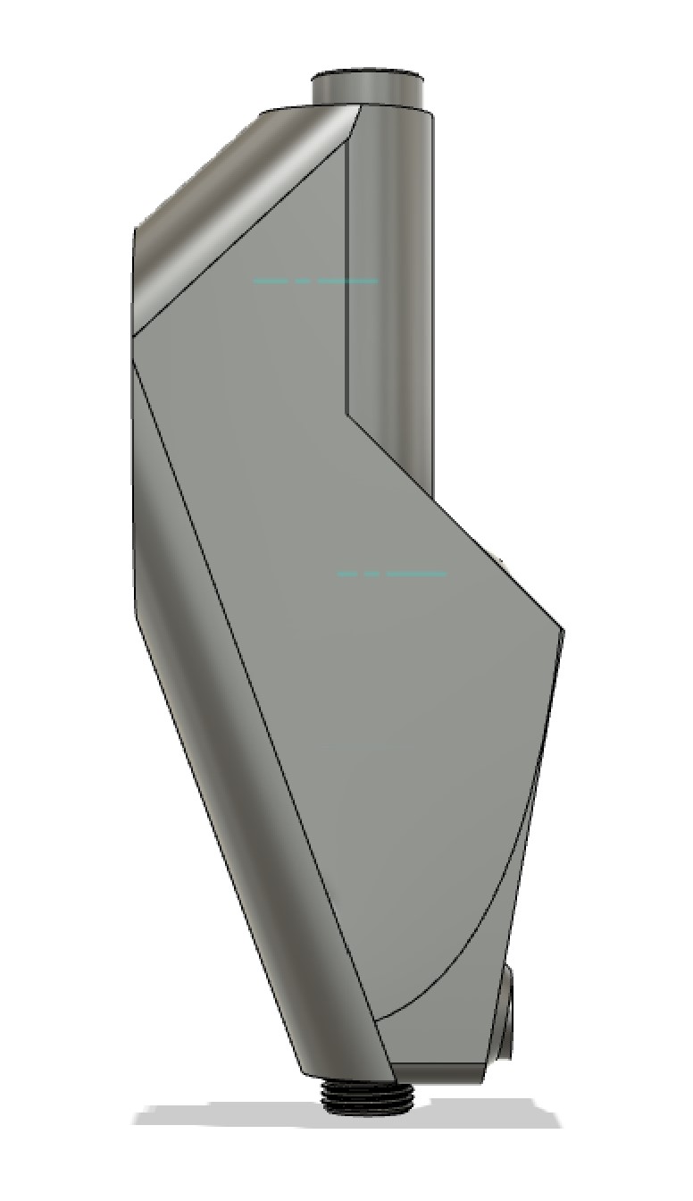
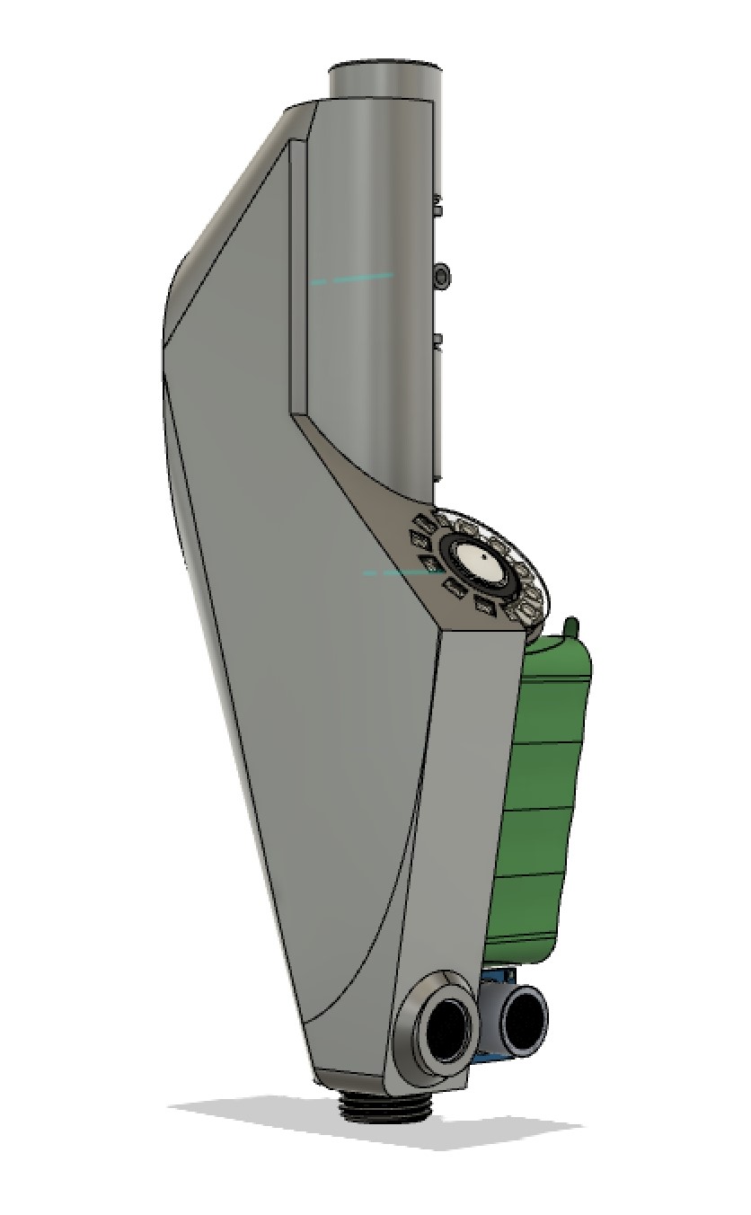
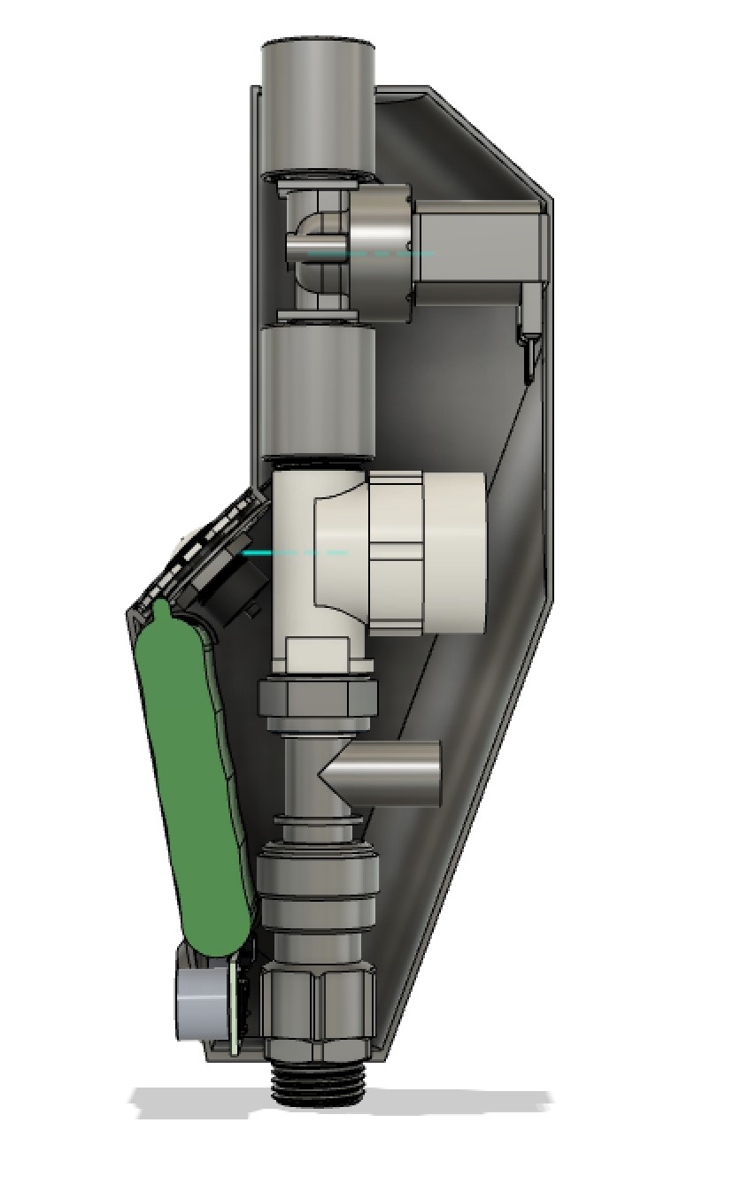
During the last couple of days we have iterated quite a bit on the housing. We used CAD modeling and 3D printing to test out the different forms.
From each iteration we took the qualities we liked from previous iterations and incorporated. In the end we created a more complex shape; one where the shape support the different compartments without wasting much space.
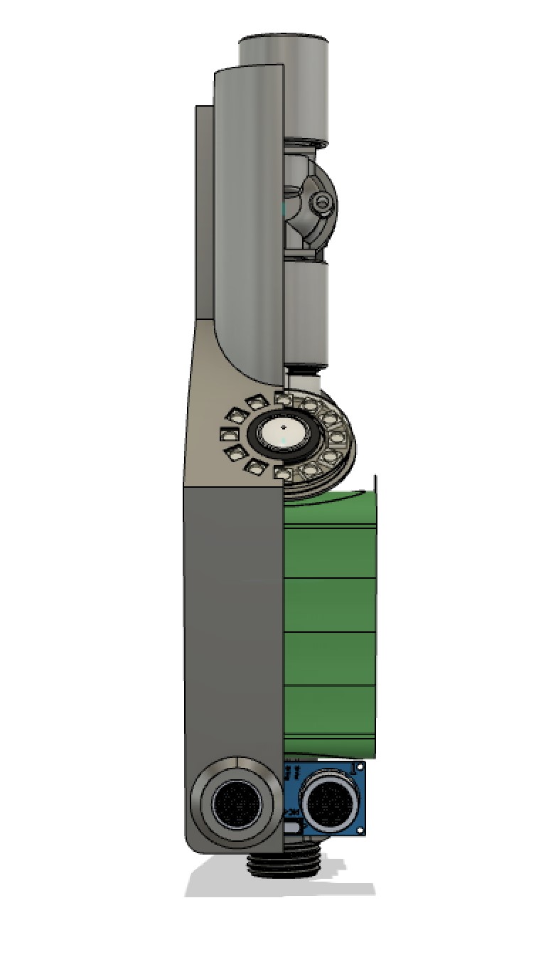
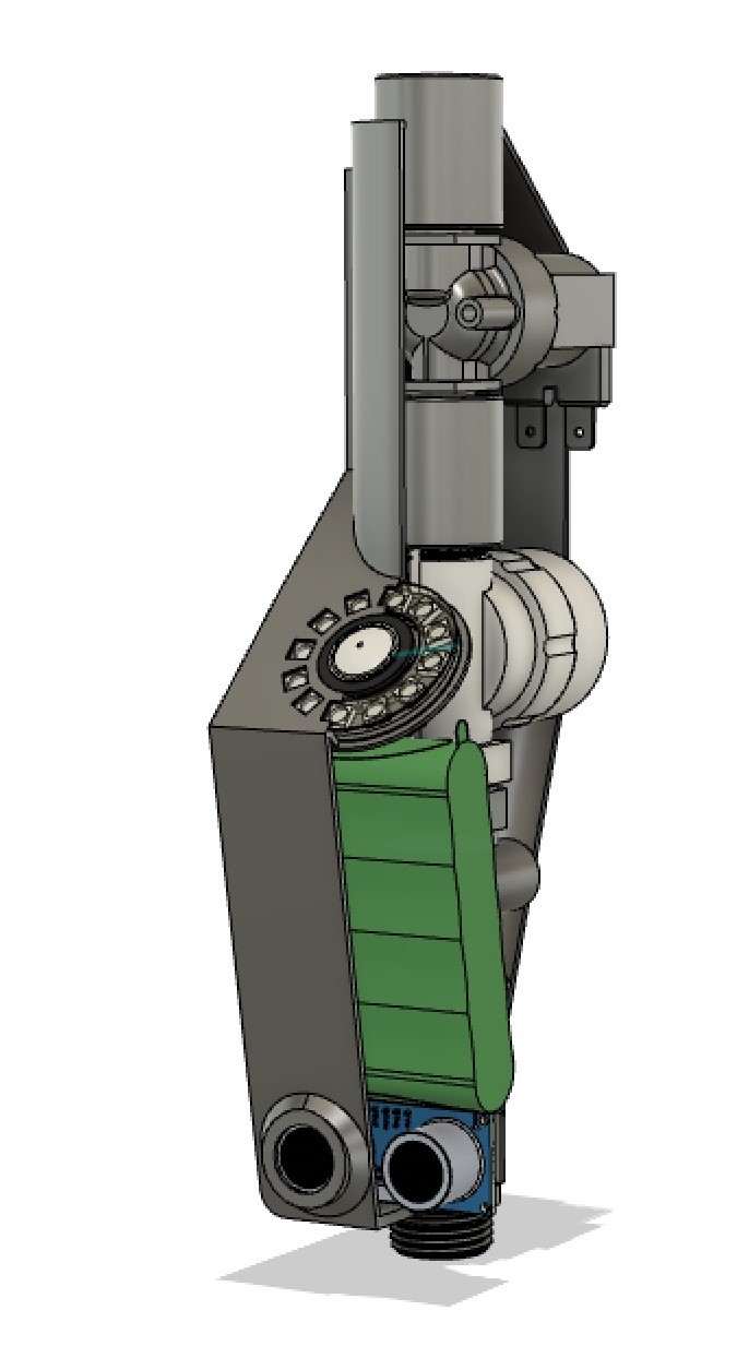
Today we got the rest of the subsystems integrated into the full system. Now the only systems that we are missing is the flow measurer and the ultrasonic sensor.
The subsystems that work with the integrated system at the current time is: The valve, the temperature sensor, the LED display ring, the button and the power supply.
We started today with setting clear goals we needed to reach by the end of the day.
The team was split into 4 groups; one group looking into further shell printing, one group working on getting the code and components to be fully integrated, one group making the storyboard for the product showcase video and one group looking into the data log in the UI.
We were still missing the Flow measurer. The goal before next sprint would be to fully integrate all of the subsystem (apart from the flow measurer) into the full system. One of the more challenging components to integrate was the motion sensor. We previously found that the sensor would only work on 5V. The ESP we use can only output 3.3V which means that the sensor would not work with the current setup. If we were to get all of the components to work on the same ESP we would need a whole new board that supports 5V. Because the deadline is coming up soon we decided to simply use an arduino slave to give the 5V output while still running the code through the ESP. This means that an extra board would need to fitted into the current prototype.
In conclusion we got the code and mechanical components to work together in the integrated system.
We had planned to start filming the video at the start of the next sprint. This meant that we would need to have a rough storyboard ready to make the filming process more smooth. We made the storyboard firstly by brainstorming and paper sketching. We simultaneously wrote a rough script.
The final storyboard was made in PowerPoint.
The current state of the data log is that it outputs the correct data minus the flow data. We also made a new iteration of the shell as the old one could not quite fit all of the components.
Last sprint ended with all of the components being successfully integrated into the full system. What we needed to do now was to simply fit the systems into the shell. Because of the unforeseen use of an extra arduino board the back of the build bulked out a bit. This had no effect on the functionality of the prototype.
When starting next step of the process; to film the product showcase video, we ran into the one thing that should not happen. The faulty flow sensor began to leak and flooded the entire prototype. Luckily not many of the systems got damaged. Nothing we didn't have spares of. This would push back the filming of the video a day and we would have to rebuilt the prototype again the next day.
.png)
Conceptualization, co-responsible for the motion sensor, housing modeling, product testing
Conceptualization, responsible for the database, NodeRed and UI
Conceptualization, responsible for the display and lights, co-responsible for the button
Conceptualization, responsible for the housing - inner and outer shell
Conceptualization, responsible for the valve and the integrated system, co-responsible for the flow measurer and the button
Conceptualization, responsible for the blog, lead producer of the showcase video, co-responsible for the motion sensor and the flow measurer